NEMA L14-30R Wiring Diagram: How to Install in a Shed
NEMA Wiring Schematic Guide for Electrical Experts
About 70% of electrical failures within facilities result from substandard wiring techniques. Such data accentuates the need of following set guidelines, spotlighting NEMA wiring schematics’ significance for electrical professionals. By means of these drawings, wiring setups that meet both operational effectiveness and supreme protection norms are presented.
The purpose of this guide is to equip electrical professionals with profound knowledge into NEMA standards. Stressing the value of correct electrical arrangements is crucial. By mastering these guidelines, practitioners can significantly cut the risk of accidents and guarantee they meet safety measures supported by Installation Parts Supply. Understanding of l 14-30 plug is vital whether creating modern setups or repairing existing ones, as it boosts the ability to deliver secure and trustworthy electrical systems.
Notable Observations
- NEMA wiring diagrams are crucial for guaranteeing electrical protection and conformity.
- Proper wiring techniques can minimize electrical failures significantly.
- Comprehending NEMA criteria boosts the efficiency of electrical arrangements.
- Installation Parts Supply promotes compliance with regulatory standards in electrical operations.
- NEMA diagrams cover a broad spectrum of uses across various sectors.
Grasping NEMA Norms and Their Significance
NEMA standards are essential in the electrical sector, guiding protection and functionality precisely. Developed by the National Electrical Manufacturers Association, they establish pivotal criteria for designing, evaluating, and marking electrical equipment. Such measures guarantee consistency and reliability across all electrical configurations, which is invaluable.
Which Are NEMA Criteria?
NEMA designations span from grades 1 to 13. Each level delineates the criteria necessary for electrical appliances to perform efficiently. Such as, NEMA 1 delivers minimal indoor protection but is missing dust resistance. Alternatively, NEMA 4 secures equipment is watertight, a requirement for withstanding considerable water immersion. Understanding these designations is essential in selecting proper appliances.
Why NEMA Criteria Are Important for Electrical Safety
The impact of NEMA standards in maintaining electrical safety is significant. They are instrumental in minimizing shock risks, device malfunctions, and fire hazards. Proper adherence to NEMA standards empowers appliances to perform safely under specific environmental conditions. For outdoor deployment, NEMA 3 ratings deliver protection against the environment, safeguarding the apparatus from harsh conditions like precipitation and blizzard conditions. In zones prone to explosions, classifications such as NEMA 7, 8, and 9 are vital for maintaining protection.
Uses of NEMA Criteria in Wiring Drawings
The implementation of NEMA criteria in wiring drawings is crucial for safe, optimal electrical systems. These diagrams utilize standardized symbols and formats based on NEMA classifications, simplifying the interpretation of complex electrical arrangements. This standardizing is advantageous. It fosters clarity, standardization, and minimizes errors, thus improving electrical safety across residential and industrial sectors.
NEMA Wiring Diagram Essentials
NEMA wiring schematics are crucial for electrical specialists, ensuring complicated linkages clear. They detail the junctions and components in various setups. By understanding the parts, types, and icons of NEMA diagrams, professionals can enhance their performance in installations and maintenance.
Constituents of NEMA Wiring Drawings
NEMA diagrams comprise key components for distinct electrical installations. You’ll see wiring connection points, interfaces, and additional equipment for reliable junctions. Every piece guarantees energy is spread optimally, following safety protocols.
Varieties of NEMA Wiring Schematics
NEMA uses various schematics, like connection blueprints and electrical designs. Schematics outline equipment relationships, while arrangements illustrate power flow. Choosing the correct drawing aids in troubleshooting and setup.
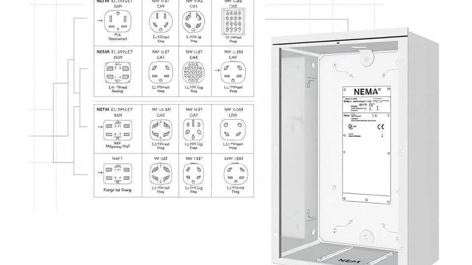
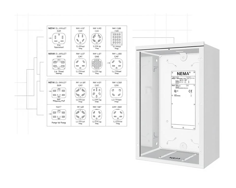
Typical Icons Used in NEMA Wiring Diagrams
Icons in wiring drawings are essential for clear clarity. They illustrate toggles, loops, and interfaces. Understanding these notations helps crews interpret schematics correctly. This ensures setups comply with NEMA criteria.
NEMA Wiring Schematic Characteristics
For electrical professionals, comprehending the key elements of detailed electrical wiring drawings is crucial. These diagrams provide both clarity and wholeness, synchronizing setups with NEMA criteria. They necessitate exact marking and proportioning to reduce installation errors. This fosters a more secure and highly efficient operational setting.
Key Features of Precise Electrical Wiring Drawings
Correct electrical wiring schematics are vital in electrical initiatives. They encompass key attributes such as:
- Transparency: Diagrams must be straightforward, minimizing misinterpretation risks.
- Completeness: They need to contain all essential components, connections, and electrical ratings.
- Conformance: Following NEMA criteria is mandatory for ensuring safety and functionality.
- Detailed Labeling: Distinct labels on each component are essential for grasping and avoiding mistakes.
- Accurate Proportions: The scales should reflect the real setup to portray the arrangement correctly.
Comprehending NEMA Coupler Layout
The insight into NEMA connector configuration is vital for making accurate junctions in electrical setups. Awareness of specific pin arrangements ensures safety and appliance performance. There is a diversity of NEMA couplers, intended for distinct voltages and flows, including:
| Connector Model | Amperage Rating | Voltage Rating |
|---|---|---|
| L5-15 | 15A | 125V |
| L5-20 | 20A | 125V |
| L14-20 | 20A | 125/250V |
| L1430C | 30A | 125/250V |
| L620C | 20A | 250V |
| L1430C | 30A | 125/250V |
| L630R | 30A | 250V |
Grasping NEMA connector configurations is crucial for secure junctions, improving efficiency. It’s critical to align interfaces with appliances properly using rotary-lock or flat blade types, to prevent dangers.
NEMA Device Wiring
NEMA device wiring encompasses diverse setups for secure electrical device connections. These rules ensure that equipment operate in unison securely, reducing danger. Understanding the diverse NEMA equipment and their wiring is crucial for electricians.
Multiple Categories of NEMA Units
NEMA classifies units by kind based on voltage and amperage requirements. Primary setups are:
- 2-Pole, 2-Wire
- 2-Pole, 3-Wire with Grounding
- 3-Pole 3-Wire
- 3-Pole, 4-Wire with Grounding
- 4-Pole, 4-Wire
- 4-Pole 5-Wire Grounding
These setups are employed in domestic settings and factories, handling 125V, 208V, and 480V.
NEMA Plug Wiring Outlined
NEMA plug wiring varies to suit multiple power needs, with rotary-lock types providing consistent junctions in shaky conditions. For example, the L5-15 plug is rated for 15 A, common in business sites, whereas the L14-20 is designed for 20 amperes at 125/250 voltage.
The NEMA labeling convention aids in selecting the appropriate plugs, highlighting attributes like polarity and earthing. Such accuracy secures that appliances operate securely.
NEMA Outlet Wiring Guidelines
Correct wiring of NEMA receptacles conforms to electrical standards and safety norms. For instance, L530R receptacles should be wired for 30 A at 125 volts, with L630R variants for 250 voltage. Proper grounding is vital to dodge electrical mishaps.
Opting for certified NEMA plugs and sockets secures secure, code-compliant installations. It’s imperative to check authoritative guidelines when installing.
NEMA Motor Wiring and Uses
NEMA motor wiring is crucial in electrical systems, especially for commercial use. Knowing how NEMA motor configuration works secures that motors are installed for best performance. Motors, like one-phase and three-phase models, require proper wiring to work safely and optimally.
Summary of NEMA Motor Wiring
Comprehending NEMA motor wiring necessitates knowledge of connections and setups. Most three-phase motors now support dual-voltage, signifying they can work on both low (208-230V) and high voltage (460V). High voltage wiring makes a motor use less current than at low voltage. The benefits of high voltage comprise smaller wires for the supply, a major benefit for units over 10 HP.
While both NEMA and IEC appliances are used in the market, NEMA variants are generally larger and priceier than IEC ones for under 100 HP deployments. NEMA starters span size 00 to 9, fit for diverse uses. A common characteristic in NEMA trips is a Trip Rating of 20, intended to activate when a motor’s amperage goes beyond 6-fold the rated current in 10 seconds.
Opting for the Correct NEMA Motor Setup
Choosing the appropriate NEMA motor arrangement affects system performance and safety. A common three-wire control circuit utilizes three wires for a start/stop pushbutton station, enabling straightforward motor management. Frequent three-phase arrangements include the 12 Lead Dual Voltage and 6 Lead, facilitating Wye and Delta configurations.
IEC motor starters commonly feature phase loss detection, enhancing safety. They also include adjustable Trip Classes for customized protection in low voltage operations. Moreover, many units have heat protection, vital for single-phase and Dual Voltage systems.
| Arrangement | Voltage Type | Current Rating | Typical Use |
|---|---|---|---|
| 12 Lead Dual Voltage | Dual Voltage (208-230V / 460V) | Motor size dependent | Wye Start – Delta Run applications |
| 6 Lead | Single/Dual Voltage | 32 amps maximum | Both Wye and Delta arrangements |
| Single Phase | Single-level Voltage | Varies (1-5 amps adjustment) | Applications with Two Speed, Two Winding |
| Delta Connection | High-Power Voltage | Variable | Current Transformers, multiple configurations |
Conclusion
Grasping NEMA wiring schematics and norms is vital for electrical professionals looking to boost their expertise and follow electrical safety norms. These standards guarantee secure and high-performing electrical installations but also prevent risks associated with faulty wiring. As discussed, complying with NEMA standards results in the improved functionality of various NEMA appliances and systems.
For technicians, the availability of quality materials can significantly impact the outcome of their work. Installation Parts Supply provides a wide range of wiring products in accordance with NEMA criteria. This allows professionals to obtain critical components for fulfilling these significant regulations. High-quality resources and comprehensive knowledge of NEMA wiring diagrams greatly enhance installation safety and efficiency.
Throughout electrical installations, always put safety and precision above all. Mastering NEMA norms offers the knowledge necessary for implementing industry standards correctly. This secures that each electrical junction established meets high-quality norms.
Common Questions
Which are NEMA wiring drawings?
NEMA wiring drawings showcase the arrangements and linkages of NEMA-standard electrical devices. They follow safety and functional standards set by the National Electrical Manufacturers Association.
How are NEMA norms crucial for electrical safety?
NEMA norms are key to defining safety and performance benchmarks for electrical equipment. These standards assist electrical experts lower electrocution risks, device malfunctions, and burn dangers.
Which elements are crucial in a NEMA wiring schematic?
Essential components in a NEMA wiring diagram include circuit setups and junction blueprints. These schematics also offer comprehensive annotations and depict the electrical system’s various parts accurately for setups.
What types of NEMA wiring drawings are used?
Various NEMA wiring schematics serve diverse needs, including energy distribution layouts and component interconnection schematics. Every design fulfills a specific role in electrical installations.
What are common symbols used in NEMA wiring schematics?
Common symbols in these drawings represent controls, circuit breakers, outlets, and additional components. Employing these symbols facilitates unambiguous communication and accurate analysis of wiring diagrams.
Identify the key characteristics of correct electrical wiring drawings?
Correctness in electrical wiring diagrams is defined by their clarity, completeness, and explicit marking. They should conform to NEMA standards to prevent mistakes in installation.
What is a NEMA connector configuration?
A NEMA connector layout outlines electrical linkages at a connector, indicating specific pin assignments. This secures reliable and effective junctions in electrical networks.
Identify the different kinds of NEMA devices?
NEMA appliances comprise various electrical outlets and interfaces, like connectors and receptacles. They are designed for various amperage and voltage criteria to satisfy unique operational demands.
In what way is NEMA plug wiring configured?
NEMA plug wiring depends on defined amperage and voltage levels needs, following security protocols and code compliance for multiple electrical applications.
Which standards are there for NEMA receptacle wiring?
Standards for wiring NEMA sockets stress complying with electrical codes, securing accurate electrical polarity, and selecting correct wire sizes. This ensures both safety and operation in electrical setups.
What is the method to wire a NEMA motor efficiently?
To wire a NEMA motor, one must understand its specific one-phase or tri-phase setup. Selecting the correct wiring technique is crucial, in addition to practicing electrical safety for enhanced motor performance.
Which factors should be considered when opting for a NEMA motor configuration?
Selecting a NEMA motor arrangement requires an assessment of the application’s energy requirements and performance traits. It’s also vital to ensure alignment with existing equipment for assured performance and security.